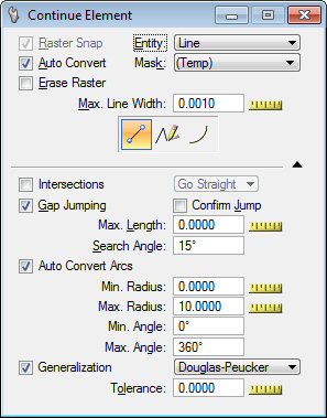
Continue Element tool settings
| Setting | Description |
|---|---|
| Raster Snap |
Use Raster Snap On/Off to open or close the raster snap capability. A raster snap is the placement of an accepted data point at a specific location on the closest raster element of an image. |
| Auto Convert |
Used to open or close the Auto Convert capability. |
| Erase Raster |
If on, the raster in the selected extent will be erased. |
| Entity |
Lets you determine where to place the nodes.
|
| Mask |
Used to select the color mask . The drop-down list shows the existing mask that can be chosen. |
| Max. Line Width |
Used to determine the maximum width of raster lines. All lines, or parts of lines, or any raster object wider than this value will not be considered as a raster line. This value is given in pixels. Use the Measure tool to measure the width of the larger lines you want to convert. |
| Intersections |
If this option is on, the following engine will not stop at the intersections. The user can select the "Go Straight", "Turn Left" or "Turn Right" options. |
| Gap Jumping |
Use to set the Maximum Gap Length and the Searching Angle. Use the MicroStation Measure Distance tool to estimate the gap length. Line breaks will automatically be bridged according to the settings you specified. If a line is located within the specified distance and angle, the gap jumping procedure will continue. If no line is found, the procedure is stopped. |
| Confirm Jump |
When this option is ON, the vectorize engine stops after it performs a jump and waits for user input to continue. |
| Auto Convert Arcs |
If on, this feature tries to recognize arcs along the line strings generated with the convert function. |
| Generalization |
If on, when a vector line is generated by automatic line conversion, it is passed through a generalization process. This process removes points from the original result to keep only those considered as necessary to characterize the original pathway of the vector line. The following options are available:
|
| Tolerance |
Use to enter the tolerance factor:
|